Valvistor Proportional Throttle Valves
Danfoss Vickers HFV (Hydraulic Feedback Valvistor) range of slip-in cartridge valves uses a self-regulating hydraulic design for the control of flow rate by a current-controlled PWM signal. The design achieves servo-type control of the main poppet without using an electrical feedback transducer.
The construction and features of these valves open up a wide range of applications with hydraulic cylinders and motors. Such applications include ie casting, deep drawn presses, injection molding, container handling, shovel loaders, forestry and dump trucks. With the addition of HFV valves to the established ISO 7368 (DIN 24342) cartridge valves, Danfoss has further enhanced an already comprehensive range.
Valvistor Technology
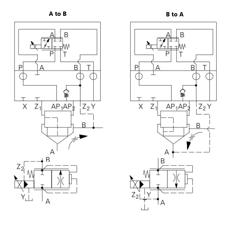
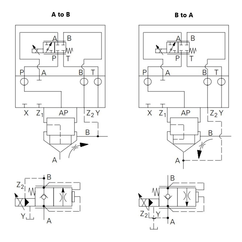
In Valvistor designs a main poppet amplifies a small flow through the pilot circuit, comparable to a transistor. Thus the name Valvistor, derived from valve and transistor. Figures 39 and 40 show the contruction of proportional throttles to ISO 7368. In both cases a Vickers type KTG4V-3S proportional valve is used as the pilot control valve. KBTG4V3S-EN427 and KBFTG4V-3SEN427 can also be used as pilot valves. Hydraulic position feedback is obtained by providing the main poppet with a longitudinal slot (5) in its cylindrical surface. This slot, together with a metering edge inside the sleeve, forms a variable orifice between the inlet of the valve and the volume above the main poppet (3). When the valve is closed and the main poppet is seated, the variable orifice area is almost closed.
Figure 39
Contruction for flow direction A to B; poppet in the closed (no flow) condition. (Note: for flow A to B, poopet drilled from A.)

Figure 40
Contruction for flow direction B to A; poppet partially open. (Note: for flow B to A, poopet drilled from B.)

Basic Characteristics
| Nominal Sizes: | |
| ISO 7368 | DIN 24342 |
| 06 | NG16 |
| 08 | NG25 |
| 09 | NG43 |
| 10 | NG40 |
| 11 | NG50 |
| 12 | NG63 |
Maximum Operating Pressure: 350 bar (5000 psi)
Flow Ratings: Up to 2160 lpm (571 USgpm)
As the main poppet opens, the variable orifice area increases. The slot is a part of one leg of a hydraulic bridge circuit and provides an internal position feedback. With the pilot throttle valve closed (figure 39), there is no pilot flow through the closed-off slot in the seated poppet. The pressure above the main poppet (3) is equal to the pressure at the valve inlet (1), due to the controlled small opening at the variable orifice. As the upper area of the poppet is greater than the area facing the inlet (1), the poppet is held against its seat (6) by a force proportional to the difference between valve inlet and outlet pressures.
Opening the pilot throttle valve lowers the pressure in volume (3) allowing the main poppet to move off its seat. As this occurs the slot passes the metering edge (7), opening the variable orifice and allowing flow through the pilot circuit. Initially the flow through the pilot valve equals the flow through the slot plus the volume displaced by the opening movement of the main poppet. The main poppet moves upwards until the pressure drops across the slot and the pilot effects a force balance on the poppet. The poppet is then held in a steady-state condition with equal flow across the slot and the pilot.
If the flow through the pilot valve is reduced (by reducing the command current to the solenoid), the force balance of the main poppet is again disturbed and the main poppet moves downwards reducing the slot area and decreasing flow to the upper chamber until the force balance is restored. Thus by controlling flow through the pilot valve, the main poppet can be controlled in any position from fully closed to fully open. In this manner a very simple, effective servo-control of the main poppet is obtained. If the outlet pressure exceeds inlet pressure when the pilot valve is closed, the main poppet allows reverse flow (see CVCS model code). The main valve function is determined by the type of pilot fitted.
Features and Benefits
The HFV range with its simplicity, cost effectiveness and performance level can be applied in almost all applications from high performance industrial areas such as injection molding to those applications just requiring proportional functionality.
If pressure compensation is added to the pilot stage, the complete valve is pressure compensated. If a pilot relief valve is fitted, the main stage operates as a relief valve. As the pilot flow is returned to the valve outlet (i.e. no “drain” connection) the valve is energy efficient. Therefore the position of the main poppet is controlled by a closed-loop system with a variable orifice in the poppet acting as the internal position feedback element. The command signal in this feedback system is pilot flow, as set at the proportional pilot throttle valve (4).
In addition, the HFV range offers:
| Unequalled simplicity | No inner electrical feedback loop and associated electronics |
| Two models: for flow direction A to B or B to A | Provides system design options and flexibility |
| Free flow in reverse direction | Provides system design options and flexibility |
| Poppet valve construction | Provides tight shut-off and load holding |
| Internal pilot flow | Simple installation and energy efficient |
| Very fast response | Provides the system designer with high dynamic acceleration/velocity/deceleration profiles for demanding performance requirements such as: • Cylinder position control including lift/lower • Rotary actuator dynamic control • Velocity profile control |
| Smooth closing and opening | Shock-free start-up and shut-off allow high velocities to be maintained for longer periods, thus reducing cycle times |
| Low hysteresis | 8% to 1% depending on pilot valve used |
| Integral feedback | Internal hydraulic feedback provides effective, low-cost position control of main poppet |
| Repeatability | Provides repeatable and accurate actuator velocity to a given operator command input |
| Electrical operation | Current-controlled PWM signal |
| Pressure compensation | Can be achieved by pressure compensating pilot stage only |
| Cost-effective design | Provides multiple functions such as pressure compensation, flow control and reverse free flow check valve |
| Optional manual override | Pin design |
| Compatible with anti-wear hydraulic oils and phosphate esters (non alkyl) | Flexible application for broad range of installations |
| Electrical connections DIN or conduit box | Provides design to meet OEM or user preference |
Valvistor Proportional Throttle Valve Functions
Complete valve assembly comprises insert, cover and proportional solenoid operated pilot valve (pilot valve to be specified and ordered separately).

Models without free reverse flow capability
Use cover type CVCS-**-HFV*-W-*2(9)-1*
Direction of controlled flow A to B: Use insert type CVI-**-HFV-20-A-***-1*
Direction of controlled flow B to A: Use insert type CVI-**-HFV-20-B-***-1*

Models with free reverse flow capability
Use cover type CVCS-**-HFV*-*2(9)-1*
Direction of controlled flow A to B: Use insert type CVI-**-HFV-20-A-***-1*
Direction of controlled flow B to A: Use insert type CVI-**-HFV-20-B-***-1*


