Pressure Relief and Venting Functions
Cartridge relief valve covers feature manual pressure setting adjustment with a choice of adjusters, i.e. micrometer (M), micrometer with key lock (K), or standard square end screw with hex. locknut (W). Additionally, venting, unloading, and remote piloting are possible. Alternative arrangements include integral electrical selection of pressure or venting and of dual pressure settings and venting. Electrically proportional control is also available.
The cartridge insert consists of a sleeve, a seating poppet (area ratio 1:1), and a closing spring. It is retained in the manifold cavity by a control cover which contains the manually adjustable pilot valve and all piloting connections. An ISO 4401, size 03 (ANSI/B93.7M-D03) mounting interface for pilot control valves or modules is optional. Cartridge valve characteristics can be matched to application requirements by adding suitable orifices in the pilot circuit. Relief valve arrangements described in this catalog can be built into system manifold assemblies with directional flow regulating and pressure reducing functions in cartridge form.
System Relief Valve
ISO 7368, B-xx-2-B specifies an interface strictly for use with main system relief valves. This interface differs from ISO 7368, B-xx-2-A, only in the position of the orientation pin which prevents any other valve function from being inadvertently installed where a system relief valve should be used. Danfoss-Vickers introduces system relief valve covers, type CVCS-xx-SC(x) in compliance with ISO 7368, B-xx-2-B. This is in addition to existing relief covers type CVCS-xx-C(x) which conform to ISO 7368, B-xx-2-A.
Maximum Operating Pressure
Up to 350 bar (5000 psi), dependent on the maximum pressure of any pilot valve or module used.
Pressure Adjustment Range
3 to 125 bar (43 to 1800 psi)
5 to 250 bar (72 to 3600 psi)
8 to 350 bar (116 to 5000 psi)
Maximum Recommended Flow Rates
Nominal sizes ISO 7368 (DIN 24342):
06 (NG16): 255 L/min (67 Usgpm)
08 (NG25): 590 L/min (155 Usgpm)
09 (NG32): 1250 L/min (330 Usgpm)
10 (NG40): 1700 L/min (450 Usgpm)
Control Data
Manual pressure adjustment is located in the control cover. A vent connection is provided for optional remote control by suitable pilot pressure or pilot directional control valve(s).
Pilot Control Flows for Maximum Pressure
| Nominal valve size ISO 7368 (DIN 24342) | Flow rate through main valve L/min (USgpm) | Pilot flow in L/min (USgpm) for pressure at the A(P) port of 350 bar (5000 psi) |
| 06 (NG16) | 50 (13.2) 230 (60.1) | 1.60 (0.42) 2.00 (0.53) |
| 08 (NG25) | 20 (5.3) 1.15 (0.30) 200 (52.8) 550 (145) | 1,50 (0.4) 1.70 (0.45) |
| 09 (NG32) | 25 (6.6) 1.14 (0.30) 200 (52.8) 680 (180) | 1.60 (0.42) 1.75 (0.46) |
| 10 (NG40) | 25 (6.6) 1.28 (0.34) 400 (105.7) 700 (184.9) | 1.60 (0.42) 2.00 (0.53) |
General Information
The pressure relief function is obtained by using a model D10 or C10F (1:1 area ratio) insert poppet and either a model C or C3 cover. Zero leak function to have no leakages from pilot to B line is also available using D10Z & C10FZ (ratio 1:1) spool. The C3 cover includes a mounting pad for a pilot valve with an ISO 4401, size 03 (ANSI/B93.7M-D03) interface. Single or double solenoid pilot valves are applicable. A model CVGC-3 module is available for use with dual solenoid pilot valves to obtain two pressure settings and a vent (both solenoids deenergized) condition.
For main system relief functions use model type SC, SC3. Electrically controlled proportional pilots provide infinitely variable pressure settings over a wide pressure range, achieved by using either a D3 cover or a remote pilot. In each configuration the Z1 port is used as a vent port or for remote hydraulic control. A suitable remote control is the CGR-02 valve. Port Z1 should be blocked when not required. Port Y is a drain port.
When the insert’s B port goes directly to tank the Y port can be connected to it. However, any back pressure in the B port is additive to the pressure setting. If there are pressure surges in the B port, the Y port should be directly drained to the tank through a separate line. All functions are available in sizes 16, 25, 32 and 40.
Pressure Relief Functions
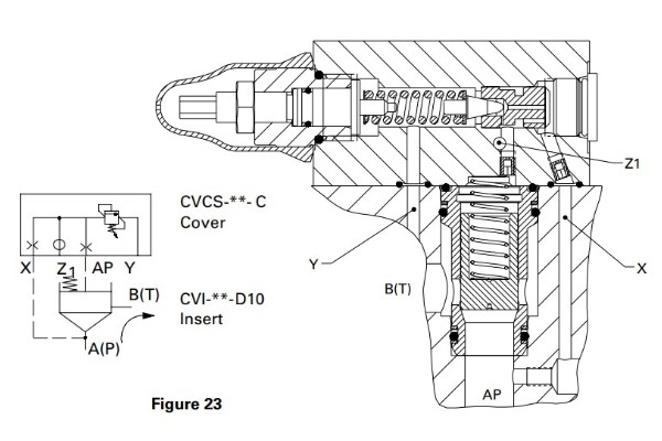
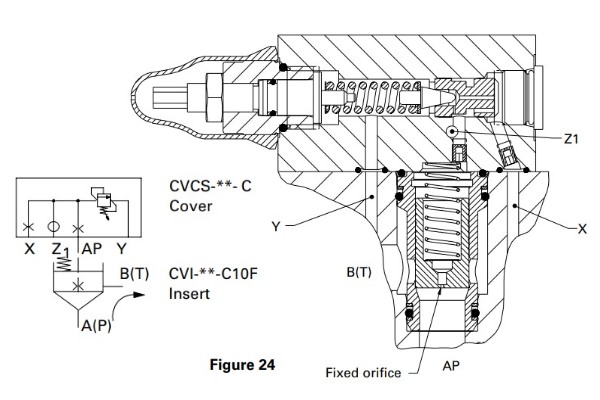
Operation of both types D10 and C10F is similar: System pressure at A(P), Figures 23 and 24, is determined by manual pilot adjustment. Orifices in AP and X ports dampen poppet reaction time, preventing instability. Connecting port Z1 to tank (via an appropriate remote control valve) vents the system pressure at port A(P) to a level equivalent to insert poppet spring load plus override pressure.

Pressure Relief Function (no internal orifice): Sizes 16 to 40
Type D10 has no internal orifice and requires pilot connection A to X to be made in the manifold block. Type D10 insert has good response combined with low shock characteristics and is recommended for general use.

Pressure Relief Function (fixed orifice): Sizes 16 to 40
Type C10F has a fixed orifice connecting port A to the pilot relief stage, allowing through-spool piloting for faster response. The higher response characteristics of type C10F can be further enhanced by the addition of the connection A to X within the manifold block. System shock generation is dependent on the usual factors of trapped volume, system pressure and flow rate.

Pressure Relief and Single Solenoid Pilot Valve: Sizes 16 to 40
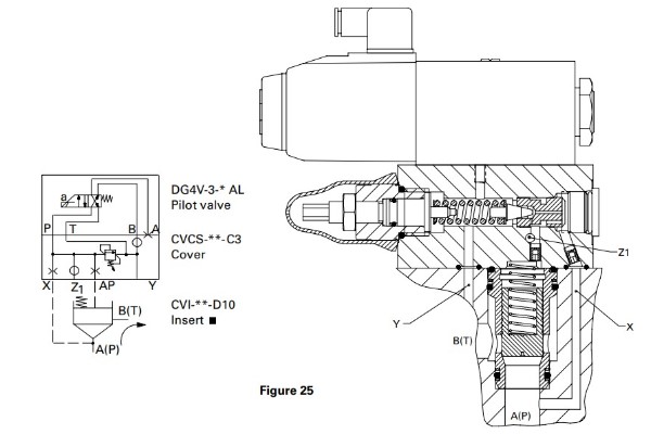
When the solenoid is de-energized, Figure 25, the cartridge is vented. When the solenoid is energized, pressure at port A(P) is limited by the setting of the adjuster in the cover. A left hand pilot valve arrangement is shown. A right hand model would allow venting when the solenoid is energized.

Pressure Relief and Dual Solenoid Pilot Valve: Sizes 16 to 40
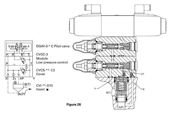
The CVGC-3 module, Figure 26, controls low pressure which occurs when solenoid “a” is energized. Solenoid “b” is energized to obtain the high pressure set by the adjuster on the C3 cover. When both solenoids are de-energized, system pressure is vented to the reservoir.


