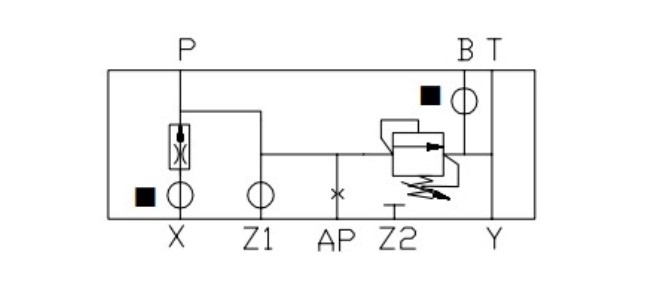
Function X - Pressure reducing
The basic pressure reducing cartridge features manual adjustment of reduced pressure plus a pilot port for optional remote control. Additional options include electrical selection of high and low pressure, and electrohydraulic proportional control of reduced pressure. Reducing valve arrangements described in this catalog can be built into system manifold assemblies with directional, manually adjustable flow restrictor and pressure relief functions in cartridge form. The reducing function is available in sizes 16, 25, 32 and 40.
Unlike other cartridge valve inserts, the reducer insert contains a spool rather than a poppet. Therefore, no reference is made to an area ratio in relation to reducing valves. The reducing valve is normally closed. It varies flow to provide a constant outlet pressure below that of the inlet pressure. The pressure differential between inlet and outlet must be at least 5 bar (72 psi) for optimum reduced pressure control for low flows.
System pressure at B is communicated through a compensated flow control in the X or X3 cover into area AP. This flow control maintains a constant flow across the cover poppet, independent of the main flow from B(P1) to A(P2), thereby providing pressure stability at all system flow rates. Load pressure transients are relieved through the check valve located in the insert spool and are limited by the pilot pressure control in the cover.
The Z1 port is used for remote control of the reduced pressure. Suitable remote controls are the C-175 and CGR-02. Venting of the Z1 port will cause outlet pressure A(P2) to drop to a minimum pressure related to the spring load in the insert spool. The Z1 port should be blocked when not required. The Y port is used to drain the pilot oil.
Pressure Reducing with Manual Adjustment and Remote Control: Sizes 16 to 40
Reduced pressure at A(P2) is controlled by the manual adjuster in the cover. Pilot port Z1 is used for remote control.
